


“Lesson of the Lens” - Learning to build on our own according to the proposed drawings: Lesson-presentation in physics on the topic “Lens. Main optical axis. What is a lens? Hold up the images of the subject. The use of lenses. converging lens. The object is between the focus and the double focus of the diverging lens; F< d < 2F. Строим вместе.
"Lens" - The main designations in the lens. Lenses in a camera. Biconvex (1) Plano-convex (2) Concave-convex (3). Lens - Optical transparent body bounded by two spherical surfaces. Construction in a diverging lens: Concave lenses are: If the object is between the focus and the optical center, then the image is virtual, direct, enlarged.
"Converging lens" - ? We found out the main properties of wonderful rays in a converging lens. Main beams for a converging lens. Lenses that convert a parallel beam of light rays into a converging one: O1 - the center of curvature of the surface. The optical power of the lens. R is the radius of curvature of the surface. Consider the refraction of rays in a plano-convex lens.
"Distance and scale" - Solve the problem. If the scale is given by a fraction with a numerator of 1, then. What does the ratio 1:5000000 mean? Microorganism Daphnia. On a map with a scale, the distance is 5 cm. Algorithm for finding the distance on the ground: Model fire truck on a reduced scale. The distance between the two cities is 400 km.
"Distance" - Departure point: Saint Petersburg. Route sheet. During the years of the Great Patriotic War the city withstood a 900-day blockade. Calculation of distance from Novgorod to the point of arrival. Saint Sophia Cathedral. Alexandrian column. Travel time calculation 1. Departure point: Saint-Petersburg city Transfer point: Novgorod city.
"Building an image in a lens" - 1. What is a lens? 2. What kinds of lenses do you know? 3. What is the focus of a lens? 4. What is the optical power of a lens? 5. What is light? 6. How is light depicted in optics? Construction of images in a converging lens. Building an image in a diverging lens. Real Inverted Diminished. Construct the further course of the beam in the prism.
GOAL OF THE WORK: Determining the focal length of a converging lens.
BRIEF THEORY. geometric optics based on law rectilinear propagation light in homogeneous media and on the laws of reflection and refraction of light. The concept is also used light beam. A light beam is a geometric line along which the energy of electromagnetic waves propagates.
Refraction at a spherical boundary. On fig. 1 shows the course of paraxial rays from a point source S 1 through a spherical interface between two media with refractive indices n 1 and n 2 ; i 1 - angle of incidence, r 1 - angle of refraction. At point S 2 an image is obtained.
Accepted next rule signs: distances are measured from the top ABOUT spherical surface; segments that are deposited against the course of the rays are recorded with a minus sign, along the beam - with a plus sign; the segments that are deposited along the perpendicular to the optical axis up are recorded with a plus sign, down - with a minus sign; the angles are measured from the optical axis S 1 S 2 , the angles of incidence and refraction - from the normal; if the countdown goes clockwise, then the angle is recorded with a plus sign, counterclockwise - with a minus sign.
It can be seen from the drawing that: , g= -r 1 +u 2 , , , Based on the law of refraction for paraxial rays:
n 1 i 1 \u003d n 2 r 1, n 1 (u 1 -g) \u003d n 2 (u 2 -g) or
Points S 1 and S 2 , which are the centers of homocentric sheaves that are transformed by this system, are called conjugate points. Relation (1) is called the equation of conjugate points.
The value is called the optical power of the spherical surface.
 The optical power of the lens.
A lens is a body of transparent material that is bounded by two spherical surfaces. Such lenses have an axis of symmetry called the main optical axis. We will consider the lens as an ideal optical system. An ideal optical system gives an image of a point source in the form of a dot. A sufficiently good approximation of an ideal optical system can be a centered system if paraxial beams fall on it. In what follows, only ideal optical systems are considered.
The optical power of the lens.
A lens is a body of transparent material that is bounded by two spherical surfaces. Such lenses have an axis of symmetry called the main optical axis. We will consider the lens as an ideal optical system. An ideal optical system gives an image of a point source in the form of a dot. A sufficiently good approximation of an ideal optical system can be a centered system if paraxial beams fall on it. In what follows, only ideal optical systems are considered.
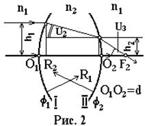
Let's build a beam path that is directed parallel to the main optical axis О 1 О 1 (Fig. 2). The medium on both sides of the lens is the same (refractive index n 1). Lens thickness d, lens glass refractive index n 2 . The point F 2 at which rays incident parallel to the main optical axis intersect the optical axis is called the focus. Let us apply equation (1) to spherical surfaces I, II and then to the lens as a whole. Let us denote the optical powers, respectively
N 1 u 1 +n 2 u 2 = f1 h 1, (2)
N 2 u 2 +n 1 u 3 = f 2h2, (3)
N 1 u 1 +n 1 u 3 = f h 1. (4)
Given that:
For thin lens(d<< R), поэтому
f = f1 + f2. (7)
Cardinal points and planes of the optical system. Let's direct the beam 1 parallel to the optical axis (Fig. 3). We continue it until it intersects with the continuation of the beam passing through the focus F 2 , we get the point K 2 . Towards the beam 1 let's direct the beam 2 . We get the point K 1 . Let us draw a plane through these points perpendicular to the main optical axis.
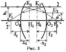 Such planes are called principal planes, and the points H 1 and H 2 are called principal points. Principal planes are the locus of conjugate points that are located at equal distances from the optical axis and are on the same side of it. This pair of planes and points is one of the main (cardinal) elements of any ideal optical system.
The location of the main points relative to the optical centers of the spherical surfaces of the lens is determined by the segments x 1 and x 2 .
From Fig. 3 it follows: ![]() . Taking into account (2), (4), (5), we get:
. Taking into account (2), (4), (5), we get:
The second pair of cardinal elements are the foci F 1 and F 2 and the focal planes that pass through the foci perpendicular to the optical axis. Focus F 2 located in image space is called back focus, focus F 1 located in object space is called front focus. The focus is the conjugate point for the point at infinity. The distance from the main point to the focus is called the focal length ( f).
The focal length is related by a simple relationship with the optical power. From fig. 3 follows:
h 1 / f 2 \u003d u 3 (10)
Taking into account (4) (assuming u 1 =0), we get:
ff 2 = n 1 , (11)
ff 1 = -n 1 . (12)
If the focal length is expressed in meters, then the optical power is expressed in diopters. An optical system has a positive optical power if its front focus F 1 lies to the left of the point H 1, and the back focus F 2 lies to the right of the point H 2 (it is assumed that light propagates from left to right).
The third pair of cardinal elements are the nodal points, which have the property that the beam (or its continuation) entering the lens through one nodal point, when leaving it, will pass through another nodal point at the same angle (in value and sign) to the main optical axis. The planes passing through the nodal points perpendicular to the main optical axis are called nodal.
For a thin lens, both principal planes coincide and pass through its optical center; therefore a 1 , a 2 , f 1 , f 2 are counted from the optical center of the lens.
EXPERIMENTAL SETUP AND MEASUREMENTS
To determine the focal lengths, an optical bench is used, on which, with the help of riders, an illuminated frosted glass with a rectangular grid, a white screen and appropriate lenses are installed.
STUDYING AND CHARACTERIZING THIN LENSES
Instruments and accessories:
1. optical bench;
2. a set of lenses;
3. illuminator;
5. a set of color filters (cr. - 6500 ![]() , green - 54001
, green - 54001 ![]() , orange - 6150
, orange - 6150 ![]() , fiol. - 45001
, fiol. - 45001 ![]() );
);
6. a set of annular diaphragms;
7. ruler.
Determination of the main focal length of optical systems.
Exercise 1. Learn from the following text how to find the focal length of the collecting optical system.
The main focal length of a converging lens can be determined by the formula:
 (1)
(1)
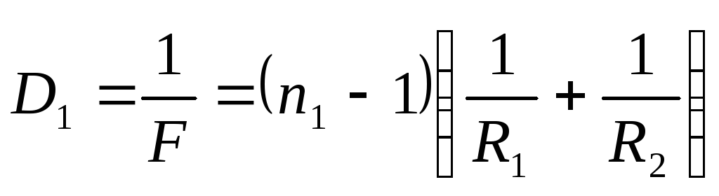
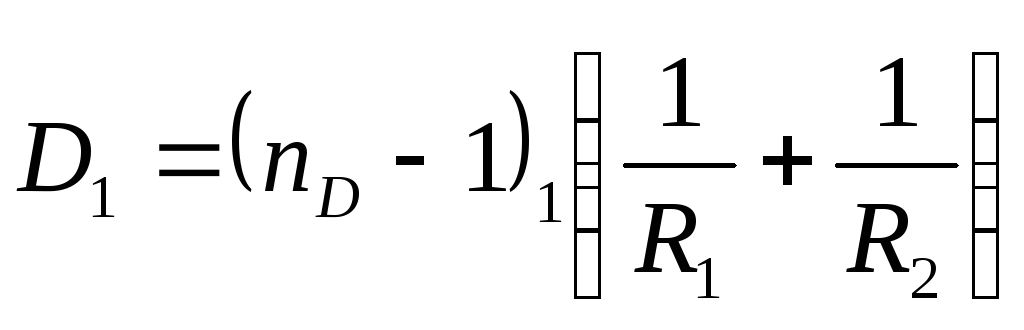
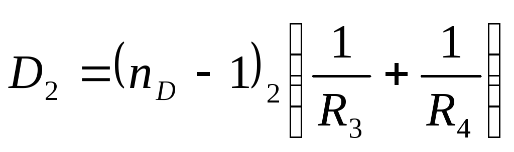
The optical power of a thin lens is determined by the formula:
 (2)
(2)
Where F is the focal length of the lens,
f - distance from the optical center to the image,
d- distance from the optical center to the object,
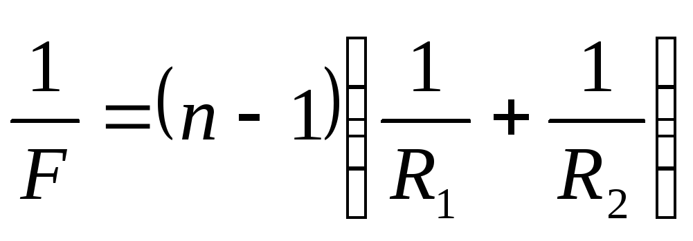
R1 And R2 are the radii of curvature of the lens,
n is the refractive index of the lens.
In formulas (1) and (2) F, F, d, R 1 And R 2 are considered positive if they are deposited from the lens along the beam, negative - if they are in the opposite direction.
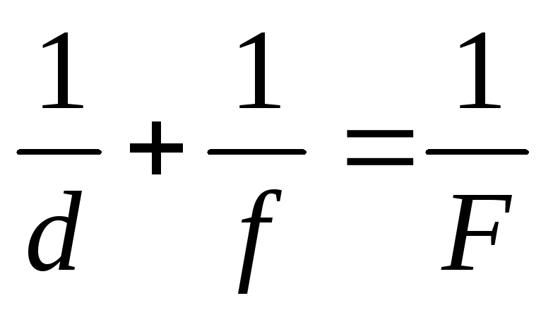
Focal length F lenses can be determined by formula (1), knowing d And F. But in practice d And F it is difficult to determine, since the optical center of the lens L, in the general case, does not coincide with the center of the system. You can proceed as follows. From formula (1) it can be seen that the quantities d And F can be interchanged, and this formula will not change its appearance. In practice, this means that if you place an object in the place of the image, then its image will turn out in the place where the object used to stand.
This can also be interpreted as follows: if, having received, for example, a sharp reverse and enlarged image of the object A "E" on the screen (Fig. 1), measure d And F, and then, without touching the object and the screen, move the lens L to L" so that the distance between L" and A"E" is equal to d.. Then on the screen we will see a sharp, reverse and reduced image of the object A"E", which will be located from L" just at a distance d.
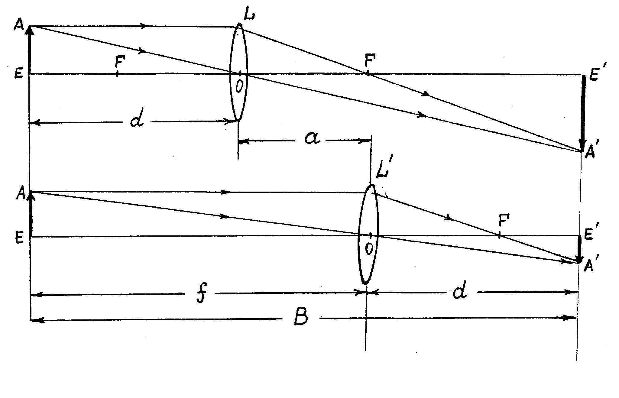
Thus, with the help of a lens, two images can be obtained: an enlarged one, located at a distance F from the center of the lens, and reduced - at a distance d, and the quantities d And F are related by formula (1). Let us denote the amount by which the center of the lens O has shifted as a. This value can be measured by moving any point of the lens O, since during its movement, the position of the optical center inside the lens does not change. The latter circumstance makes it possible to overcome the difficulty indicated above by replacing the measurement of the displacement of the optical center O with the measurement of the displacement of some pointer on the support of this lens.
From fig. 1 shows that B= f+ d; a= f- d.Adding or subtracting these expressions, we get:
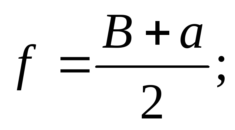
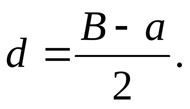
Taking into account formula (1), we have:
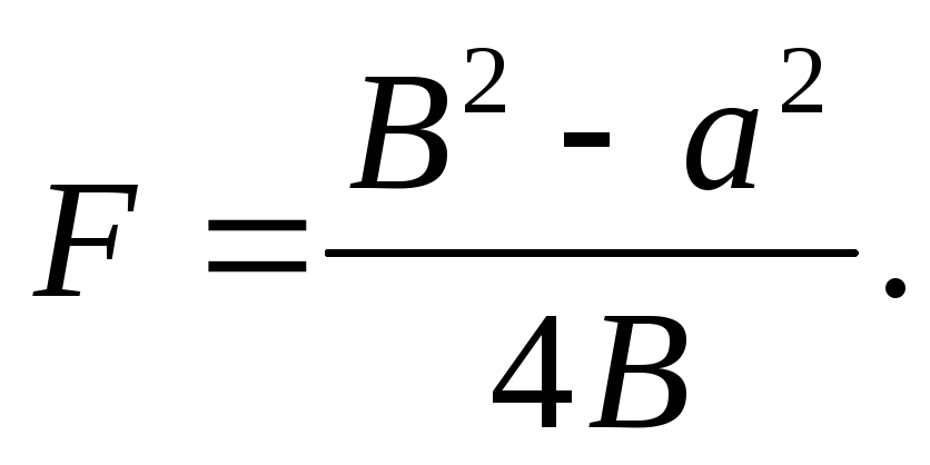 (3)
(3)
Task 2. Determining the focal length of a converging lens.
Install an illuminator, a screen and a converging lens under study between them on the optical bench. Select base B such that clear images of the object (letters "T") are obtained on the screen at two positions of the lens: once - enlarged, the other time - reduced.
With a fixed base selected, move the lens to achieve a sharp image of the object on the screen. Using a ruler, measure the position of the lens relative to the screen or source.
Move the lens at a given base until a new image of the object is obtained on the screen. Measure the distance again - from the lens to the screen or source. According to the obtained measurements a (Fig. I) and according to formula (3), calculate R. Repeat the above exercise for one lens and one value B at least 3 times. Repeat the exercise for the second converging lens. Average the measurement results, calculate the focal lengths of both lenses, estimate the confidence intervals of the found values F.
Task 3. Determination of the focal length of a system of two converging lenses.
Compose a system of lenses whose focal lengths were determined in task 2. Determine the focal length of the system using the method used in task 2. Calculate F by formula (3). Calculate the optical power of the system.
![]() (4)
(4)
where Ф 1 - optical power of the first lens,
Ф 2 - optical power of the second lens,
 - the distance between the centers of the lenses that form the system.
Task 4. Determining the focal length of a diverging lens.
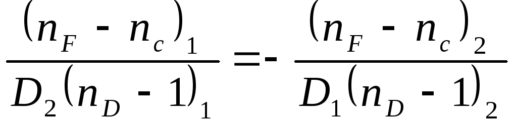
A diverging lens does not give a real image, so it is impossible to determine its focal length by the method described in task 2. Combine divergent lens with focal length F 2 with a converging lens with a focal length F 1 so that the system formed by them gives a real image. Determine the focal length of this system F With, recalculate focal lengths F With And F 1 into optical powers and using formula (5) calculate the optical power and focal length of the diverging lens.
Determination of optical errors of lenses (aberrations)
Exercise5 . Study chromatic aberration.
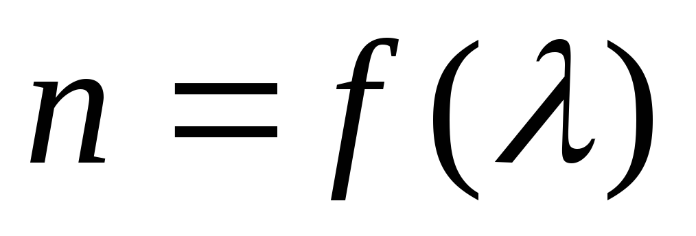
Refractive index n. matter depends on the wavelength of the incident light
 (dispersion). Since the focal length of a lens depends on the refractive index (see formula (2)), then for each of the monochromatic rays the lens will have its own focal length. But the distances from the optical center of the lens to the image plane and to the object f And d are related by relation (1). Therefore, if an object illuminated by white light is placed at a certain distance from the lens, then its sharp image will be at different distances for different monochromatic rays. By moving the screen, you cannot get a clear image of the subject. It will always be somewhat blurry and colored.
Lens errors due to the dependence of their main focal length on the wavelength are called chromatic aberrations. Chromatic aberration is eliminated by combining lenses so that different color images are combined to give a non-iridescent image in the focal plane.
Let's do the calculation for the simplest case - a system of two lenses with optical powers

 (6)
(6)
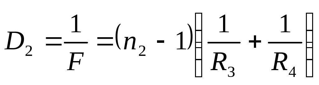 (7)
(7)
If the lenses are stacked closely, then the optical power of the system is equal to
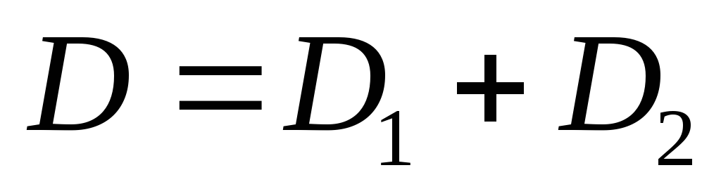 (8)
(8)
There will be no chromatic aberration if the optical power
systems  does not depend on the wavelength, i.e.
  And
And 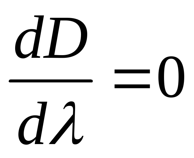 :
:
![]() (9)
(9)
It is fundamentally impossible to calculate a system that is achromatic for all wavelengths. It is possible to combine only two multi-colored images corresponding to two selected wavelengths. For visual devices (acting in conjunction with the observer's eye), such waves are chosen as  And
And 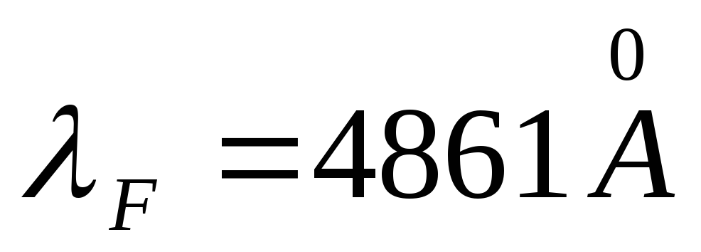 . The colors corresponding to these waves - red and green-blue - are complementary and, when superimposed, give the impression of white. For the glass of the first lens, we can write
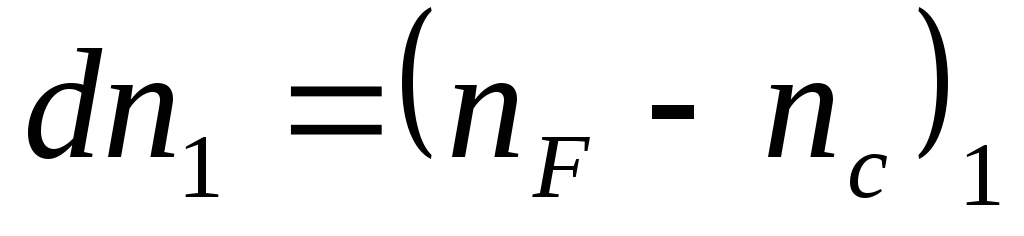 ,
,
for glass second
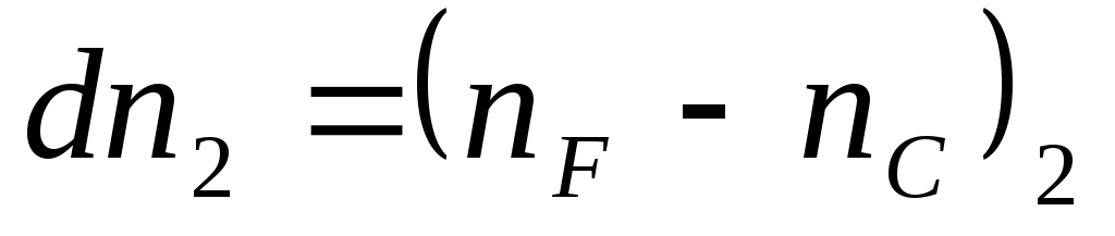
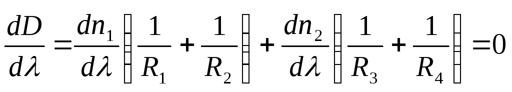
Having written formulas (6) and (7) for n 1 and n 2 corresponding to an arbitrary wavelength, for example, 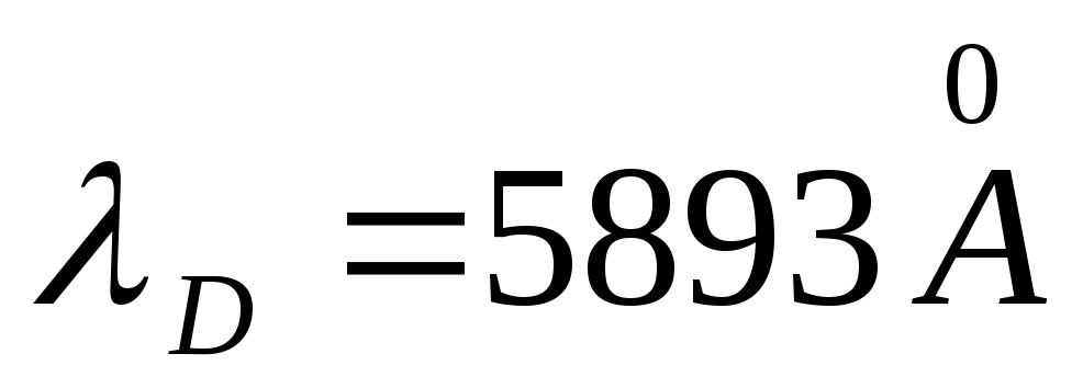 , and substituting the values
  And
And ![]() in (9), we obtain three equations:
in (9), we obtain three equations:
 (10)
(10)
 (11)
(11)
We divide both sides of the last equation by 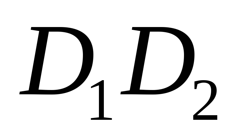 after transformations we get:
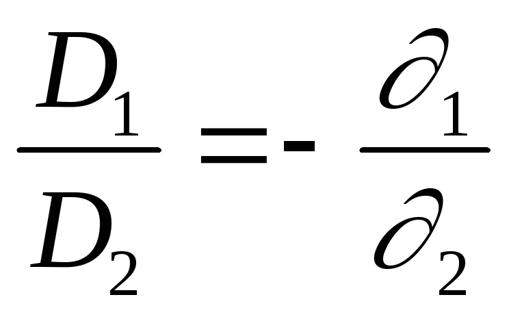 (13)
(13)
Where 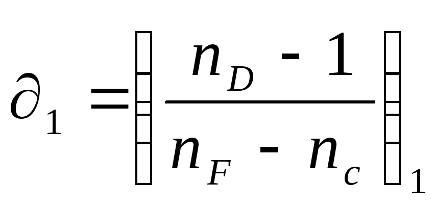 And
And 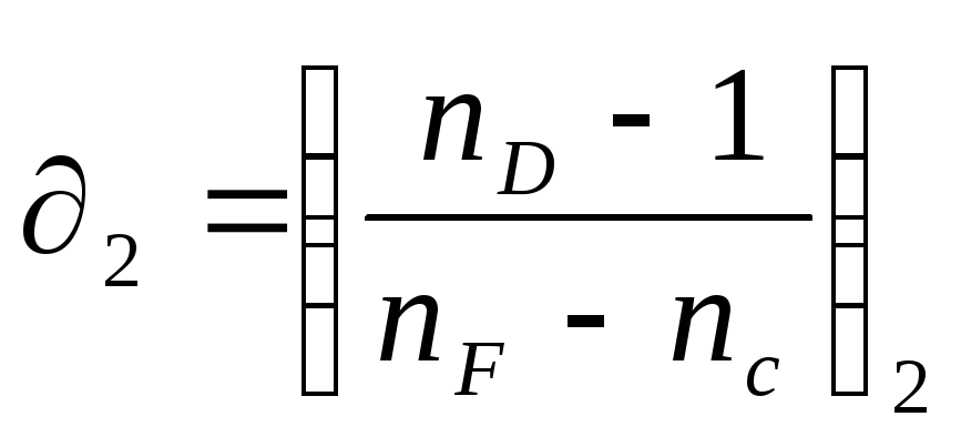 - dispersion coefficients of lens glasses. Formula (13) expresses the achromatization condition for a two-pin lens. Since the dispersion coefficients have the same signs, the “–” sign in formula (13) shows that
  And
And  have different signs, i.e. achromatization can be achieved by combining a converging lens with a diverging one. In this paper, we study the dependence of the focal length of the lens on the wavelength of the incident light. To do this, install the filter holder. It can be seen from formula (1) that if the distance is kept constant, d That
  And
And  will be proportional to each other. This circumstance makes it possible to simplify the measurements and calculations in this task. Since we are interested in the nature of dependence
  from
from  , then instead of can be measured proportional to it . Install the filter in the holder. leaving d constant, move the screen until a clear image is obtained. Changing filters, move the screen until a clear image corresponding to a given value is obtained. . measuring f, build a dependency graph f().
Task 6. Study spherical aberration.
Let diaphragm BB with a small round hole in the center (Fig. 2) select a narrow beam of paraxial rays emanating from point A. Let us replace it with diaphragm DD with an annular hole. The edge rays are more strongly deflected in the lens than the paraxial ones, and with the same position of the source A, its image will be at a smaller distance from the lens than in the first case.
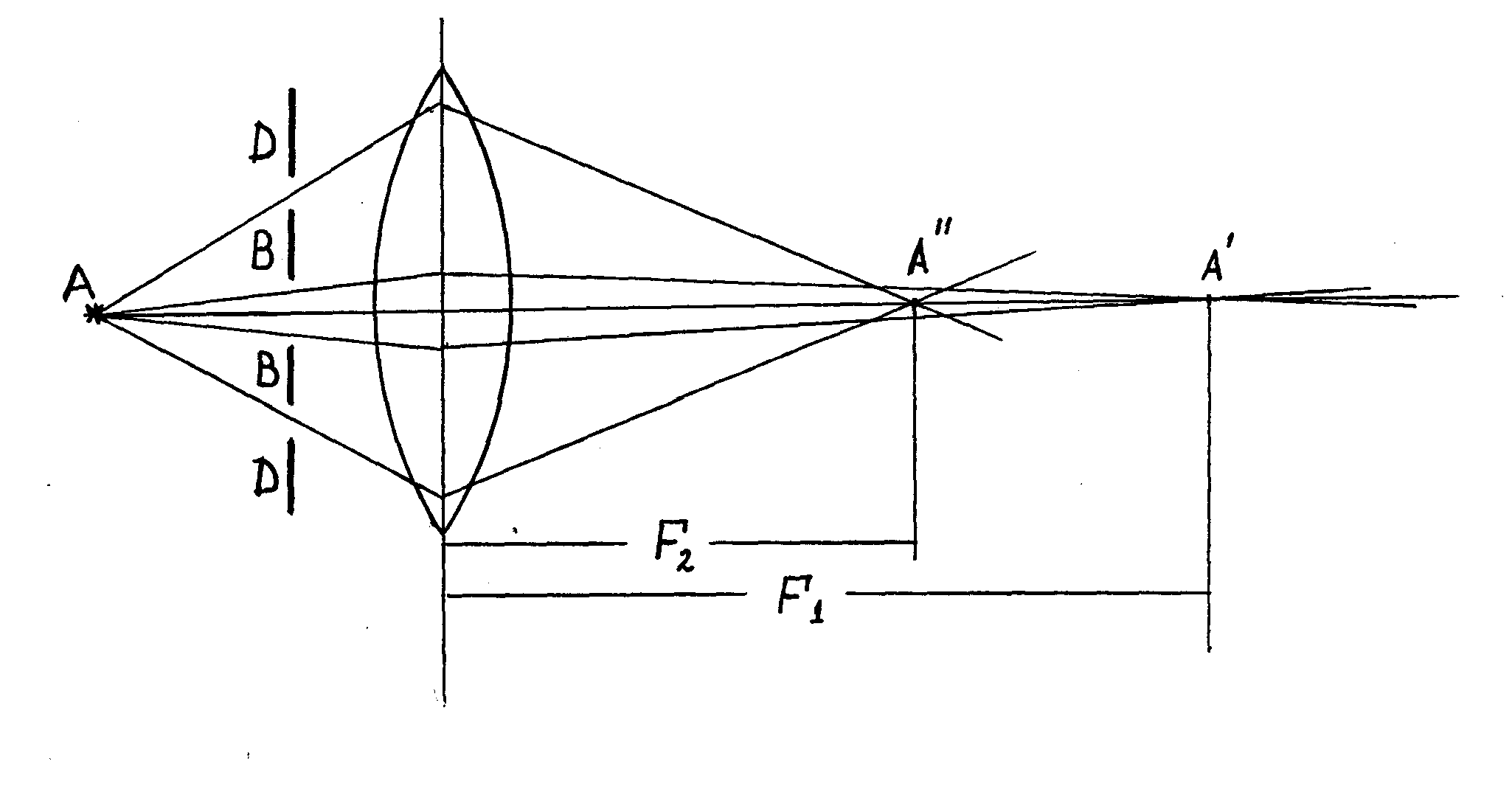 Rice. 2
Value  called longitudinal spherical aberration. It is due to the fact that different ring waves have different focal lengths and, therefore, different values f given d. Due to spherical aberration, the image of the object is blurred. Indeed, the rays from the source A, refracted by various annular zones of the lens, cross the main optical axis at various points (points A "and A") and, no matter where the screen CC is placed, point A will be displayed as a blurry circle. In one of the positions between A "and A" the diameter of the light spot will be the smallest, which corresponds to the most distinct image. Place a large converging lens. By moving the CC screen, achieve a sharp image of the subject. Install the diaphragm with an annular cutout. By moving the screen, again get the largest clear image of the subject. Repeat the experiment for different annular diaphragms, measuring the corresponding values f. Plot dependency graph
  , Where r- aperture radius. Graphs to build only on graph paper. When discussing the results of the work, pay attention to the course of dependencies
  And Compare the obtained results with theoretically expected ones.
Questions for self-study
1. The concept of a thin lens. Thin lens formula. For which rays is the lens formula applicable?
2. Main focal length. focal plane. The concept of optical power, luminosity, relative aperture.
3. Formula for the main focal length of the lens.
4. Types of lenses. List all types of converging and divergent lenses.
5. The course of rays in lenses. The concept of real and imaginary images.
6. The phenomenon of chromatic and spherical aberration. Draw the course of the rays. Elimination of chromatic and spherical aberration.
Literature
1. Landsberg G.S. Optics.
2. Saveliev I.V. Course of general physics, part 3
3. Zisman G.A., Todes O.M. Course of general physics, part 3
Lab #5
Determination of the optical power and focal length of a converging lens.
Goal of the work: determine the focal length and optical power of a converging lens.
Equipment: a ruler, two right-angled triangles, a long focus converging lens, a light bulb on a stand with a cap containing a letter, a current source, a key, connecting wires, a screen, a guide rail.
Training tasks and questions
The lens is called _____
A thin lens is _____
Show the course of rays after refraction in a converging lens.
Write down the formula for a thin lens.
The optical power of the lens is _____ D= ______
How will the focal length of a lens change if its temperature rises?
Under what condition is the image of an object obtained with a converging lens is imaginary?
The light source is placed in the double focus of a converging lens, the focal length of which is F = 2 m. At what distance is its image from the lens?
Construct an image in a converging lens.
Describe the resulting image.
Progress
1. Assemble the electrical circuit by connecting the light bulb to a current source through a switch.
2. Place the light bulb on one end of the table and the screen on the other end. Place a converging lens between them.
3. Turn on the bulb and move the lens along the rod until a sharp, reduced image of the luminous letter of the bulb cap is obtained on the screen.
4. Measure the distance from the screen to the lens in mm. d=
5. Measure the distance from the lens to the image in mm. f
6. With d unchanged, repeat the experiment 2 more times, each time getting a sharp image again. f, f
7. Calculate the average distance from the image to the lens.
f f f= _______
8. Calculate the optical power of the lens D D
9. Calculate the focal length to the lens. F F=
10. Enter the results of calculations and measurements in the table.
№
experience
f 10¯³,
diopter
diopter
11. Measure lens thickness in mm. h=_____
12. Calculate the absolute error in measuring the optical power of the lens using the formula:
∆D = , ∆D = _____
13. Write the result as D = D± ∆D D = _____
Conclusion:
computer experiment
Using the given focal length F, determine the refractive power of the lens. Enter this value into the model.
For each experiment, select the data in the table of the distance from the object to the lens, express these values in mm.
For each experiment, describe the type of image.
Record the results of these images in a table.
№ experience
Focal length F , cm
Distance from the object to the lens d, cm
Image view
Formulate and write down a conclusion about how the image of an object changes when it is moved.
READY STUDENT WORK
Lab #5
Taking an image with a lens.
Goal of the work: learn how to take different images with a converging lens.
Progress
№ experience
Focal length F , cm
Distance from lamp to lens d, cm
Image view
Direct, enlarged, imaginary
Image missing
Inverted, enlarged, real.
Equal in size to the light source, inverted, real.
Inverted, reduced, real.
\u003d 14 diopters
W 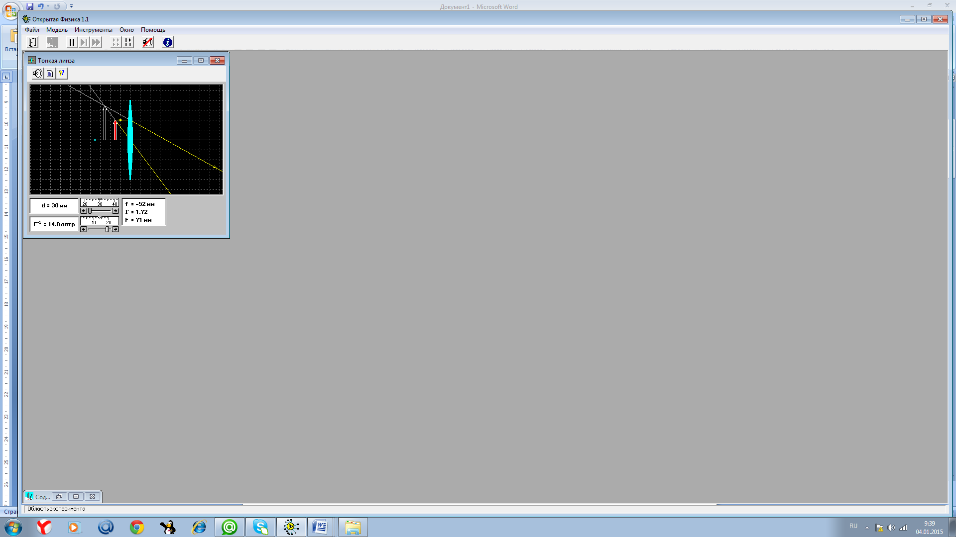 task 1
Type of image: direct, enlarged, imaginary.
W 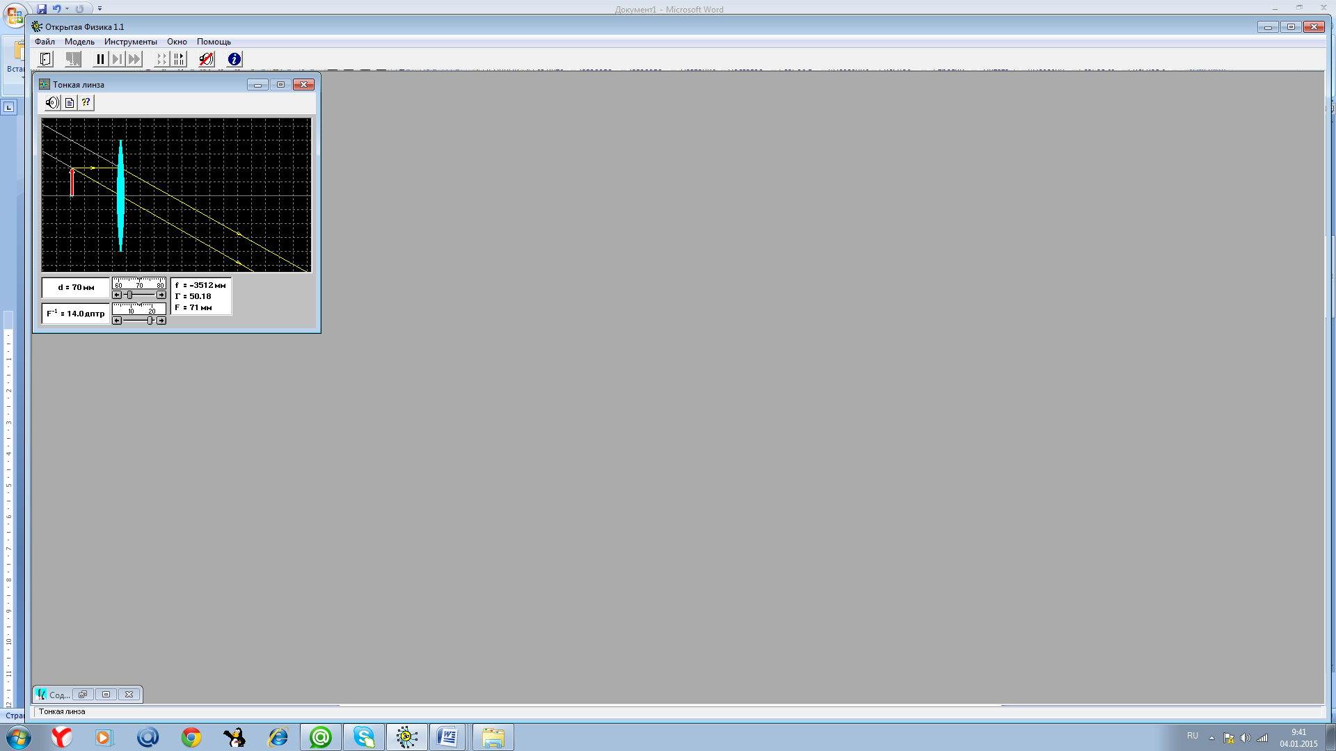 assignment 2.
Image type: no image.
W 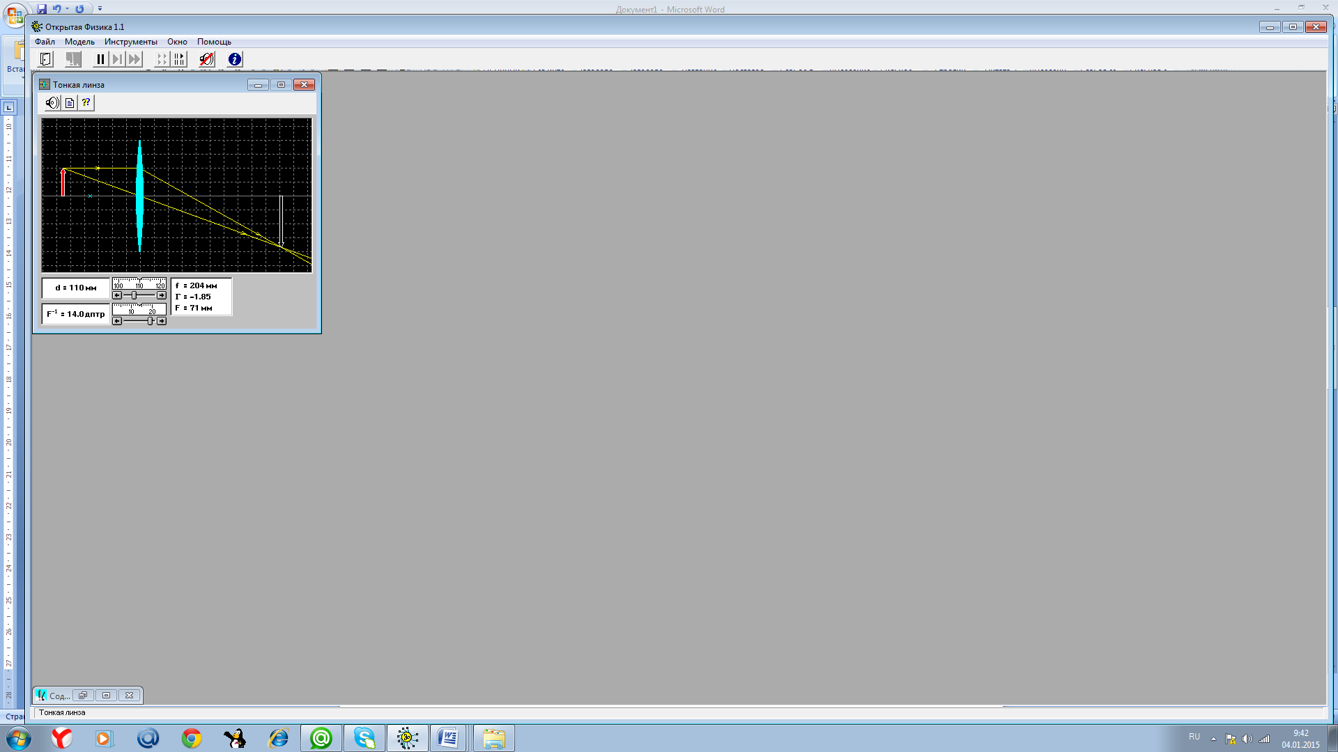 assignment 3
Image type: inverted, enlarged, real.
Task 4.
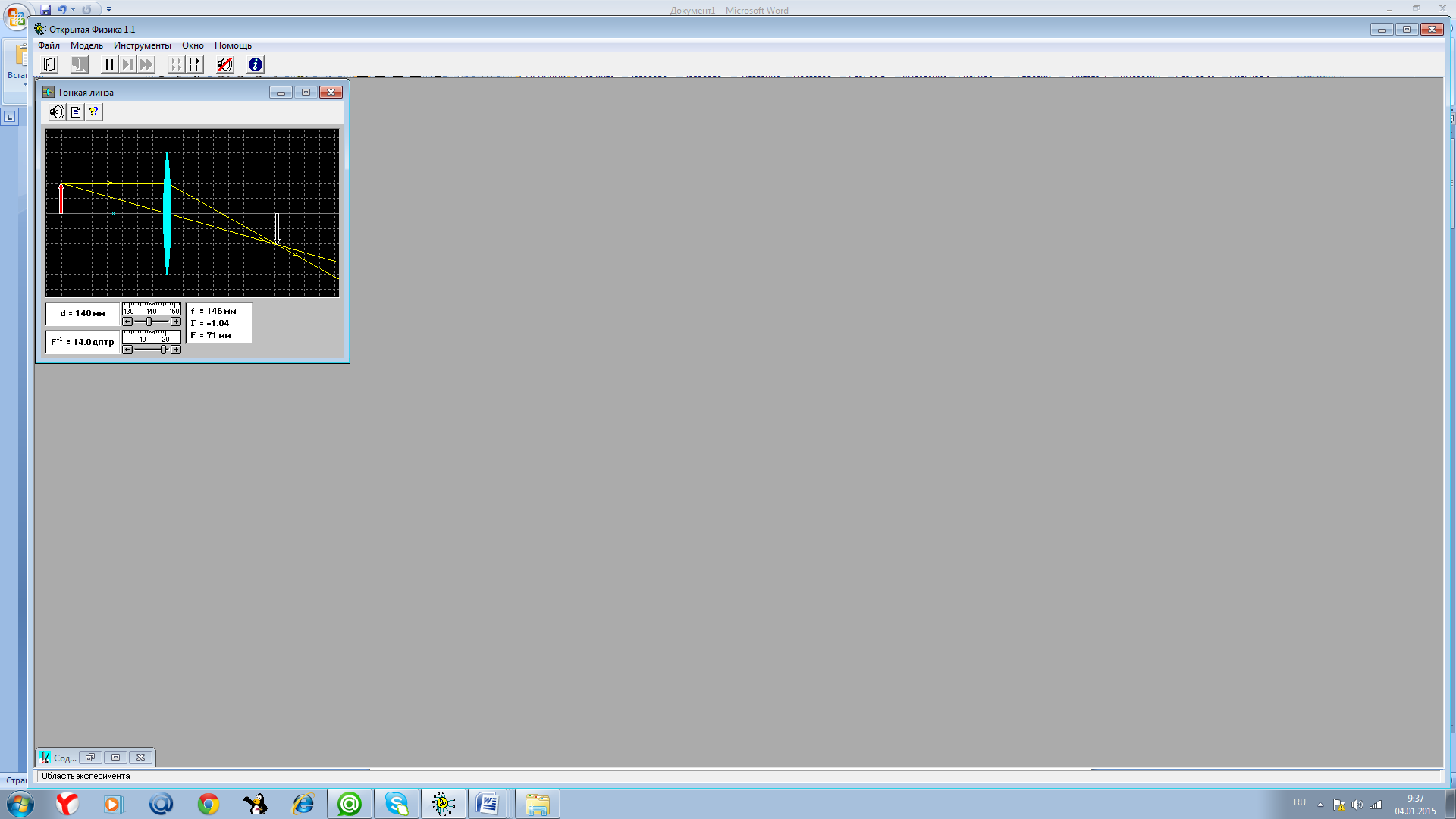
Image type: equal in size to the light source, inverted, real.
Task 5
![]()
Image type: inverted, reduced, real.
Conclusion:
1) When the light source is between the lens and its focus, its magnified, imaginary and direct image is on the same side of the lens as the light source; as the light source moves away from the lens in this segment, its image increases.
2) When the light source is in the focus of the lens, its image is absent.
3) When a light source is between the focus and double focus of the lens, its image becomes a real and inverted (magnified) image. It decreases as the light source approaches the double focus of the lens.
4) The image of a light source that is in the double focus of the lens becomes an image equal in size to the light source and is in the double focus of the lens on the other side of the lens.
5) As the distance from the light source to the lens increases (d > 2F), the image of the light source decreases, remaining real and inverted, and approaching the focus of the lens.
You will also be interested in:

Childbirth is always a test for the female body, and additional surgical ...

Breastfeeding is a very important period in the life of mother and baby. This is the time of the highest...

As expectant mothers admit, especially those awaiting the birth of their first child, for the first time ...

Being with him is very interesting, but there are times when you don't know how to behave with him....

As you know, a person is not born, they become one, and the foundations for this are laid back in ...

